I have developed some automation projects for laboratories working with water, seeking to take advantage of the resources for serial communication available in several commercial instruments and equipments for laboratory.
These projects are described (in Portuguese) at: http://www.c2o.pro.br/automacao/index.html. All or them developed with the programming language Tcl/Tk and compatible libraries.
Some of that programs are dedicated to data acquisition (monitoring) while others only control an equipment (controll).
In this section we share information about the development of a system to take measurements of respirometry in sludge from aerobic wastewater treatment systems, but with potential to be used in monitoring and control of bioreactors in general.
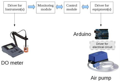
The system consists of four parts:
driver for instrument(s)
monitoring module (monitor.tcl)
control module (objcont.tcl)
driver for the equipment(s)
The two modules (monitor.tcl and objcont.tcl) use two different types of parameters:
parameters monitored during an experiment
parameters controlled during an experiment
The monitored variables (handled by monitor.tcl) are used to identify the state of the system but do not generate control events, while the controlled variables (handled by objcont.tcl) are used to generate control events (aeration, addition of reagents, heating) whose purpose is to keep these variables within a range.
The two main modules (monitor.tcl and objcont.tcl) were developed at different times, therefore they have different approaches and comments about in the source code in different languages, “monitor.tcl” is commented in Portuguese and the comments in “objcont.tcl” are in English.
The program “monitor.tcl” was developed to automate the data acquisition of a specific multiparameter. Later I did some more changes to use it with different meters from many manufacturers using modules for each instrument.
I made some more improvements to display the readings in real-time graphics with the Plotchart library and storage measures in the database using the Metakit library.
The program objcont.tcl, based on Finite State Machine (FSM) and with the TclOO package, was developed as an additional module for the monitor.tcl program to add resources for the control of equipments (pumps, heaters etc).
7.1. Automated Process Control (Urbano, Luque e Gómez-Nieto,2004)
A process can be defined as a sequence of related actions that occur during an interval of time with the goal of producing a change in a given system.
From the point of view of the process automation and control we can classify processes into two main types:
Type I - Processes that depends on the “system state”
Type II - Processes that depends on the time within which the actions are developed
In such processes the control actions are executed based on their intermediate states (Sn).
The automation of these processes depends on a continuous monitoring of the parameter(s) which interfere with the process state. So this type of control requires the use of Instrument(s) for monitoring, and Equipment(s) for the execution of control actions. [6]
In these cases the actions are taken after analysis of one or more parameters (physical and/or chemical and/or biological).
Figure 6. General model for state-dependent process. Action A-S0 executed at State S0, Action An at State Sn and so on.
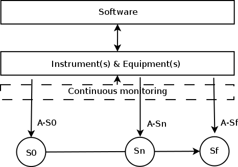
These systems must include modules with “rules” for the “decision making” during the process.
Processes in which actions are performed based solely on the time interval (t) elapsed.
In this type of process automation the control actions are executed regardless the "state (or condition) of the process but only based at time: A-t0 at t0, A-tn at tn and A-tf at the end of process (tf).
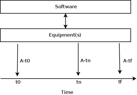
There are also cases in which both criteria (time and state) are used, and in these cases the "rules" for control uses variables based on time and state.
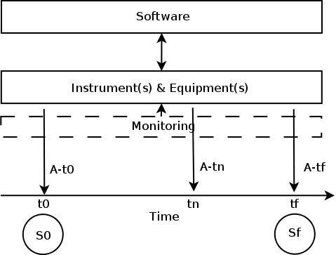
The initial state of the system, S0, is known. Then, the system is subject to a series of actions to be executed either sequentially or concurrently along an interval to reach a final state, Sf , in which the characteristics of the system are monitored again.(Urbano, Luque e Gómez-Nieto,2004)
This is the type of process used in the automation of an analytical process.
A finite-state machine (FSM) or finite-state automaton (plural: automata), or simply a state machine, is a mathematical model of computation used to design both computer programs and sequential logic circuits. It is conceived as an abstract machine that can be in one of a finite number of states.
The machine is in only one state at a time; the state it is in at any given time is called the current state. It can change from one state to another when initiated by a triggering event or condition; this is called a transition. A particular FSM is defined by a list of its states, and the triggering condition for each transition. (Source: https://en.wikipedia.org/wiki/Finite-state_machine)
Finite State Machines are used in various fields of bioscience.(A General History and Definition of Finite State Machines)
Finite State Machine is one of the techniques used to model the behavior of Reactive Systems. Examples of these systems are metro control, air traffic control and bioprocesses control.
It is based on a set of states and transitions betwen these states and their actions associated with these transitions.
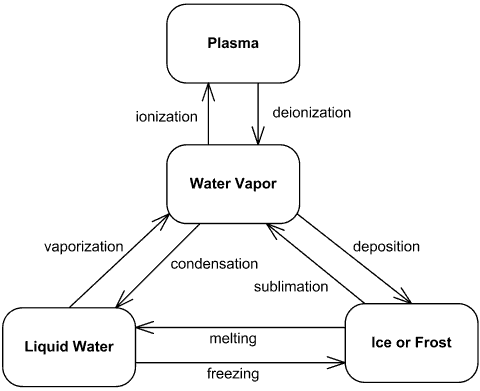
It can be represented by a graph called a State Diagram. Each of the states is represented by a node (circle or box). Edges (arrows) show the transitions from one state to another. Each arrow is labeled with the input that triggers that transition. Inputs that don't cause a change of state are represented by a circular arrow returning to the original state. For example, the figure 9 shows the state diagram for different (known) phases of water.
Figure 9. An example of state machine diagram for water phases. (Source: UML State Machine Diagram Example)
To use FSM for controling bioprocess in a bioreactor we need first to model the possible states, transitions and actions for each parameter (chemical, physical or biological) to be controlled during the bioprocess.
In this work we are designing a system for respirometric measurements in which we will make repeated measurements of oxygen uptake by the biomass in a bioreactor.
Initially the user defines the maximum and minimum limits of DO for the experiment.
Then the medium is aerated until the upper limit of Dissolved Oxygen (DO) when the aeration is stoped. From this point the measurement of oxygen uptake is initiated by the decrease of DO concentration until the lower limit of DO.
At the end of measurement of oxygen uptake the medium is reaerated until the upper limit of DO, restarting another respirometric measurement.
Sucessive measurements of respiration are done until the user stop the experiment.
Based on the DO concentration we can define three possible states:
S0 - DO <= lower_limit
S1 - lower_limit < DO < upper_limit
S2 - DO >= upper_limit
And the DO readings are the possible “Inputs” that defines the possible state transitions. And which are classified into three types of “Inputs”:
I0 - DO_reading <= lower_limit
I1 - lower_limit < DO_reading < upper_limit
I2 - DO >= upper_limit
And finally 3 types of “Outputs” (Actions) that can be triggered to turn ON/OFF an aeration pump:
IG - Ignore
OFF - Stop aeration
ON - Start aeration
Three “States” with three possible “Inputs” gives nine possible “Transitions” (3 States X 3 Inputs = 9 Transitions).
With this information we can build a table called: Symbolic State Table or State Transition Table.
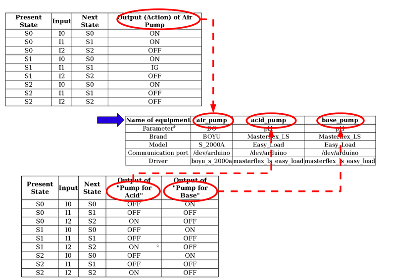
Table 1. Symbolic State Table for respirometric measurements.
| Present State | Input | Next State | Output (Action) of Air Pump |
|---|---|---|---|
| S0 | I0 | S0 | IG |
| S0 | I1 | S1 | ON |
| S0 | I2 | S2 | OFF |
| S1 | I0 | S0 | ON |
| S1 | I1 | S1 | IG |
| S1 | I2 | S2 | OFF |
| S2 | I0 | S0 | ON |
| S2 | I1 | S1 | OFF |
| S2 | I2 | S2 | IG |
The Next State is obtained from the combination of the Present State with the Input.
The following diagram (Harel State Chart) allows to visualize the three states S0, S1 and S3 related to DO concentration in a bioreactor, and the related actions to carry out measures of rate of oxygen consumption (Respirometry).
Figure 10. Harel State Chart(David Harel, 1987) of the three states of a bioreactor in relation to DO concentration. The transitions are indicated by the format “Input/Action”.
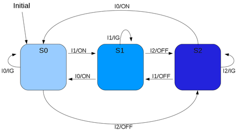
This is a Mealy State Machine because the outputs are functions of the present state AND the Input. Whereas the Moore State Machine the output values are determined solely by its current state.
Just as another example of FSM, consider a bioprocess where the pH can oscillate above or below the control limits. In this case, we need to control two pumps, one for adding acid, if pH >= pH_max, and the other to add a base, if pH <= pH_min.
In this case the “Action” of the pumps depends only on the “Final State” (Next State) and is independent of the “Inputs”(“Moore” State Machine).
Based on the pH we can define three possible states:
S0 - Acid (pH <= pH_min)
S1 - Neutral (pH_min < pH < pH_max)
S2 - Basic (pH >= pH_max)
And the pH readings are the possible "Inputs" which defines the possible state transitions. And which are classified into three types of "Inputs":
I0 - pH_reading <= pH_min
I1 - pH_min < pH_reading < pH_max
I2 - pH_reading >= pH_max
Table 2. Symbolic State Table for the control of pH.
| Present State | Input | Next State | Output of “Pump for Acid” | Output of “Pump for Base” |
|---|---|---|---|---|
| S0 | I0 | S0 | OFF | ON |
| S0 | I1 | S1 | OFF | OFF |
| S0 | I2 | S2 | ON | OFF |
| S1 | I0 | S0 | OFF | ON |
| S1 | I1 | S1 | IG | IG |
| S1 | I2 | S2 | ON | OFF |
| S2 | I0 | S0 | OFF | ON |
| S2 | I1 | S1 | OFF | OFF |
| S2 | I2 | S2 | ON | OFF |
The next step was to store the information of the Symbolic State Table (or State Transition Table) in a variable, of type dict, to map the different actions of the different equipments (pumps) to the possible transitions.
Tip
To learn a little about dictionaries see the appendix: Dictionaries in Tcl.
The command to set the dict var “state_transition_table” for respirometry (DO) has the following structure:
dict set [name_var]
 [parameter] [present_state] [input] [next_state] {[equipment] [action]}
The commands to set:
dict set state_transition_table DO S0 I0 S0 {air_pump on}
dict set state_transition_table DO S0 I1 S1 {air_pump on}
dict set state_transition_table DO S0 I2 S2 {air_pump off}
dict set state_transition_table DO S1 I0 S0 {air_pump on}
dict set state_transition_table DO S1 I1 S1 {air_pump ig}
dict set state_transition_table DO S1 I2 S2 {air_pump off}
dict set state_transition_table DO S2 I0 S0 {air_pump on}
dict set state_transition_table DO S2 I1 S1 {air_pump off}
dict set state_transition_table DO S2 I2 S2 {air_pump off}
And the command to get the values at different levels:
% dict get $state_transition_table
DO {S0 {I0 {S0 {air_pump on}} I1 {S1 {air_pump on}} I2 {S2 {air_pump off}}} S1 {I0 {S0 {air_pump on}} I1 {S1 {air_pump ig}} I2 {S2 {air_pump off}}} S2 {I0 {S0 {air_pump on}} I1 {S1 {air_pump off}} I2 {S2 {air_pump off}}}}

% dict get $state_transition_table DO
S0 {I0 {S0 {air_pump on}} I1 {S1 {air_pump on}} I2 {S2 {air_pump off}}} S1 {I0 {S0 {air_pump on}} I1 {S1 {air_pump ig}} I2 {S2 {air_pump off}}} S2 {I0 {S0 {air_pump on}} I1 {S1 {air_pump off}} I2 {S2 {air_pump off}}}

% dict get $state_transition_table DO S0
I0 {S0 {air_pump on}} I1 {S1 {air_pump on}} I2 {S2 {air_pump off}}

% dict get $state_transition_table DO S0 I0
S0 {air_pump on}

% dict get $state_transition_table DO S0 I0 S0
air_pump on
At the lowest level we get a list {equipment action} whose elements can be obtained with the command lindex $list index:
% set list_equip_action [dict get $state_transition_table DO S0 I0 S0]
air_pump on
% lindex $list_equip_action 0
air_pump
% lindex $list_equip_action 1
on
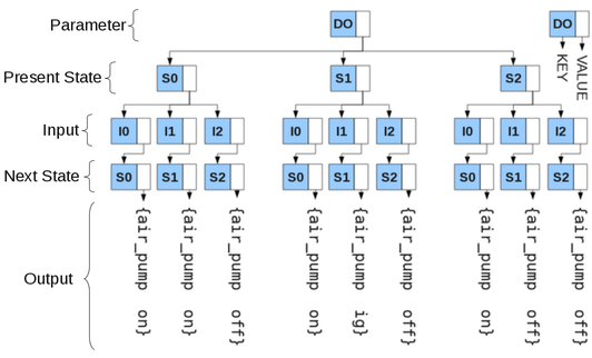
Just to help the visualization, we represent the content of state_transition_table referring to DO parameter with the following tree structure:
Figure 11. Tree structure representing the information stored in the variable state_transition_table related to the Symbolic State Table for the control of DO.
And the information in the “State Transition Table” for pH control can also be stored in the same dict variable (state_transition_table) with the following commands:
dict set [name_var]
 [parameter] [present_state] [input] [next_state] {{[equipment] [action]} {[equipment] [action]}}
  dict set 	state_transition_table pH	S0 	I0 	S0	{{acid_pump	OFF} {base_pump ON}}
  dict set 	state_transition_table pH	S0 	I1 	S1	{{acid_pump	OFF} {base_pump OFF}}
  dict set 	state_transition_table pH	S0 	I2 	S2	{{acid_pump	ON}  {base_pump OFF}}
  dict set 	state_transition_table pH	S1 	I0 	S0	{{acid_pump	OFF} {base_pump ON}}
  dict set 	state_transition_table pH	S1 	I1 	S1	{{acid_pump	OFF} {base_pump OFF}}
  dict set 	state_transition_table pH	S1 	I2 	S2	{{acid_pump	ON}  {base_pump OFF}}
  dict set 	state_transition_table pH	S2 	I0 	S0	{{acid_pump	OFF} {base_pump ON}}
  dict set 	state_transition_table pH	S2 	I1 	S1	{{acid_pump	OFF} {base_pump OFF}}
  dict set 	state_transition_table pH	S2 	I2 	S2	{{acid_pump	ON}  {base_pump OFF}}
Note
In case of needing more equipment to control a parameter, just add another pair {equipment action} to the list.
Using TclOO package, with Tcl8.5, we created the class State and a class Equipment.
The class State represents the states of different parameters to be controlled (Eg: state_DO, state_pH, state_Temperature etc.).
Note
In the case of a Respirometer the only parameter to be controlled is the DO, but we are considering a system that could be used to monitor and control many parameters during a bioprocess (DO, pH, temperature, etc.).
Tip
Digression.
The State class can also be associated to a single real monitored parameter or to a virtual parameter resulting from the interaction of various parameters by using an algorithm.
The class Equipment represents the required equipment(s) to control a parameter (Eg: air_pump, acid_pump, base_pump, heater etc). And act as an interface for communication between instances of the class State and the driver(s) of equipment(s).
Figure 12. Class diagram for the implementation of FSM for automation of bioreactors. Association between the classes State and Equipment.
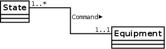
The multiplicity “1..*” in the association of State with Equipment means that an object of class State can be associated with multiple objects of the class Equipment, ie, you may need more than one device to control a parameter.
But the multiplicity “1..1” in the class Equipment means that an object of class Equipment must be associated with only a single object of class State, ie, each device is dedicated to the control of a single parameter.
The State class is endowed with the attributes:
parameter - name of parameter to be controlled
par_max - upper limit of the parameter
par_min - lower limit of the parameter
list_obj_equip - stores a list of instances of
Equipmentclasspresent_state - the present state of the system in relation to the parameter
next_start - the identifier to the scheduled command start
And the methods:
setEquip
getEquip
setState
getState
checkState
start
stop
The code to create the class State:
oo::class create state {

    variable parameter par_max par_min list_obj_equip present_state next_start

    constructor {par max min} {
	set parameter $par
	set par_max $max
	set par_min $min
    }

    method setEquip { l_e } {
    set list_obj_equip $l_e
    }

    method getEquip {} {
	return $list_obj_equip
    }

    method setState {s} {
	set present_state $s
    }

    method getState {} {
	return $present_state
    }

    method checkState {} {
	#Check if there are readout available in global variable readings.
	#If not, returns and schedule new start method

	if {[catch {set readout [getReading $parameter]}]} {
	    puts "checkState -> No readout"
	    [self] start
	    return
	}

	set readout [lindex $readout 1]

	if { $readout <= $par_min } {
	    set input I0
	} elseif { $readout > $par_min && $readout < $par_max } {
	    set input I1
	} elseif {$readout >= $par_max} {
	    set input I2
	}

	set next_state_equip_action [getInfoState $parameter $present_state $input]

	[self] setState [lindex $next_state_equip_action 0]

	set list_equip_action [lindex $next_state_equip_action 1]

	foreach {equip act} $list_equip_action {

	    foreach obj_equip $list_obj_equip {

		if {[$obj_equip getName] == $equip} {
		    after 1 [list $obj_equip sendCmd $act]
		}

	    }

	}

	[self] start
    }

    method start {} {
	set next_start [after 2000 [list [self] checkState]]
    }

    method stop {} {
	after cancel $next_start
    }
}
The attributes: parameter, par_max and par_min are initialized within the constructor.
The attribute list_obj_equip stores a list of objects of class Equipment that will be used to control parameter and is initialized by the method setEquip.
The method checkState calls the procedure getReading which reads the global variable readings, stores this information in local variable readout and classifies this “Input” in one of the three types (I0, I1 or I2).
Then calls the procedure getInfoState to get the current state and stores this information in the variable present_state.
  proc getInfoState { parameter present_state input } {

       global state_transition_table

  #Checks if there is the parameter $parameter in the state transition table

       if {![catch {dict get $state_transition_table $parameter}]} {

            set next_state_action [dict get [dict get [dict get $state_transition_table $parameter] $present_state] $input]

            return $next_state_action

       }

  }
The variable next_state_equip_action is a list of lists in which the first element is the “next_state” and the second element is a list of pairs “equipment action”. So we use a loop (foreach) to interact on the elements of list “equipment action” to call the method sendCmd for each instance of Equipment.
The Equipment class is endowed with the attributes:
parameter - name of parameter to be controlled
name - name of equipment
brand - brand of equipment
model - model of equipment
communication_port - physical communication port
channel - channel identifier to the communication port
key_channel - variable used as a “semaphore” to control access to the serial port, shared among different objects
driver - name of file which stores the information for communication between the program and Arduino™ as a Tcl loadable module (.tm)
id_after - the identifier to the scheduled command start
And the methods:
setName
getName
setCommunicationPort
getCommunicationPort
setChannel
getChannel
setKeyChannel
getKeyChannel
setEquip
sendCmd
start
stop
The code to create the class Equipment:
#Create the class equipment

oo::class create equipment {

    variable parameter name brand model communication_port channel key_channel id_after repeat

    constructor {par b m} {

	set parameter $par
	set brand $b
	set model $m
	set repeat 0

    }

    method setName {n} {
	set name $n
    }

    method getName {} {
	return $name
    }

    method setCommunicationPort { port } {
	set communication_port $port
    }

    method getCommunicationPort {} {
	return $communication_port
    }

    method setChannel {c} {
	set channel $c
    }

    method getChannel {} {
	return $channel
    }

    method setKeyChannel {k} {
	set key_channel $k
    }

    method getKeyChannel {} {
	return $key_channel
    }

    method sendCmd {c} {

	if {[info object isa object [self]]} {
	    [self] setKeyChannel [requestKeyChannel]
	} else {
	    return 0
	}

	if {[[self] getKeyChannel]} {

	    #call a procedure stored in var c which is defined in a namespace whose
	    #the name is the same as the atribute "name" of this object
	    #This "name" is not the name of object but the name of equipment used by
	    #this object

	    #to check if object exists until now
	    #or was destroyed by the command stop

	    if {[info object isa object [self]]} {
		#24/03/2014
		#As I observed the serial port (ttyUSB0) was closed suddenly I decided to include this if test

		if {[file exist [[self] getCommunicationPort]]} {

		    if {![[[self] getName]::$c $channel]} {
			closeChannel
			[self] setKeyChannel 0
			unlockChannel
			return 0
			}

		} else {

		    closeChannel

		    [self] setChannel [openChannel [[self] getCommunicationPort]]

		    if { $channel != "SERIAL_ERRO_OPEN" } {
			puts "[self] - key_channel:[[self] getKeyChannel]"
			[[self] getName]::$c $channel
			[self] setKeyChannel 0
			unlockChannel
			return 1
		    } else {
			[self] setKeyChannel 0
			unlockChannel
			return 0
		    }
		}

	    } else {
		return 0
	    }

	    #to check if object exists until now
	    #or was destroyed by the command stop
	    #set key_channel 0
	    if {[info object isa object [self]]} {
		#puts "Object [self] exists"
		[self] setKeyChannel 0
	    } else {
		return 0
	    }

	    #unlock the channel
	    unlockChannel

	    set repeat 0

	} else {

	    if {$repeat >= 5} {
		set repeat 0
		return 0
	    }

	    #schedule to make another requests
	    incr repeat
	    set id_after [after 100 [list [self] sendCmd $c]]

	}
    }


	method start {} {
	puts "[self] opening [[self] getCommunicationPort]"
    }

    method stop {} {

	#Check the existence of variable id_after which will be created
	#in the scheduling of another request

	if {[info exists id_after]} {
	    after cancel $id_after
	}

	if {[info exists channel]} {
	    [[self] getName]::off $channel
	} else {
	    puts "ERROR - [self] stop"
	}
    }
}
The constructor accepts the parameter name, the brand and model of the equipment. And the variable repeat is set to 0, which will be used to control the attempts to send commands over the serial port.
The setName method is invoked to set the name of equipment, which is stored in the global variable equipments_available.
The setCommunicationPort method is used to set the name of the physical communication port (/dev/ttySn or /dev/ttyUSBn) that will be used to send commands to the device, and which is also stored in equipments_available variable.
When starting an experiment the instance of class Equipment
must open a channel for communication and only start the experiment if the channel is open without error.
We included some if test in sendCmd to check the existence of objects using [info object isa object [self]].
The sendCmd method, called by an instance of State class, calls the getKeyChannel method to verify it has permission to send commands over the serial port.
If the return of getKeyChannel is “0” then another test is done to evaluate how many attempts have been made to access the serial port with the command:
if {$repeat >= 5} {
	puts "[info_time] [self] command $c NOT sent to [[self] getName] after 5 attempts"
	set repeat 0
	return 0
    }
If the variable repeat is greater than or equal to “5” the object returns without rescheduling. But if repeat is less than “5” it is incremented and a new schedule of the method sendCmd is done with after and stores the id of the delayed command in id_after:
incr repeat

set id_after [after 100 [list [self] sendCmd $c]]
But if the return of getKeyChannel is “1” then it tries to open the serial port:
[self] setChannel [OpenChannel [[self] getCommunicationPort]]
and sends the command to the equipment:
[[self] getName]::$c $channel
The [[self] getName] returns the name of equipment which matches the name of a namespace defined within the driver (stored in dict variable equipments_available) and the command to be sent (stored in the variable c) which corresponds to a procedure (on, off or ig) defined within the namespace of the driver.
Note
The command [[self] getName] returns the name of atribute “name” of the object equipment, and NOT the name of the object!
It is the name of equipment used by the object of class Equipment.
Is that understood?
For example, in the directory lib_equipment there are the modules: boyu_s_2000a-0.0.tm (for aeration pump) and fame_bio-0.0.tm (for a heater).
And in the module boyu_s_2000a-0.0.tm there is the namespace “air_pump” in which are defined the procedures: on, off and ig.
After sending the command to the driver is called the method setKeyChannel to set the variable key_channel to “0” and the procedure unlockChannel to release the serial device to other instances of the class Equipment.
The stop method cancels the execution of the delayed call of the method sendCmd and send the command off to the device for a safe shutdown:
 method stop {} {

	#Check the existence of variable id_after which will be created
	#in the scheduling of another request

	if {[info exists id_after]} {
	    after cancel $id_after
	}

	#	puts "Safe shutdown: [self] turning off [[self] getName]"
	if {[info exists channel]} {
	    [[self] getName]::off $channel
	} else {
	    puts "ERROR - [self] stop"
	}
    }
All information about the equipments available are stored in the variable equipments_available, of the type dict, with the commands:
dict set equipments_available air_pump par OD
dict set equipments_available air_pump brand "BOYU"
dict set equipments_available air_pump model "S_2000A"
dict set equipments_available air_pump com_port "/dev/arduino"
dict set equipments_available air_pump driver "boyu_s_2000a"
The equipement air_pump has the following features: par (parameter), brand, model, com_port (communication port) and driver.
Note
The name of the driver is the concatenation fo the brand with the model of equipment.
The commads of the driver boyu_s_2000a are stored in the module boyu_s_2000a-0.0.tm, in lib_equipment directory, and is loaded with the command:
package require boyu_s_2000a
We included the directory lib_equipment in the path of modules with the commands:
if {[lsearch [::tcl::tm::path list] [pwd]] < 0} {
  ::tcl::tm::path add [pwd]
}

::tcl::tm::path add lib_equipment/
We defined the following rules for the name(s) of equipment(s):
The name of equipment (Eg: air_pump) in
equipments_availableMUST be presente as the namespace in the driverboyu_s_2000a-0.0.tm,and MUST be the same name of the field equipment in
state_transition_table.
To get information stored in equipments_available we defined the procedures getNameEquipment and getInfoEquipment.
Procedure getNameEquipment to get the name(s) of equipment(s) related for a parameter:
proc getNameEquipment { parameter } {

    global equipments_available

    set list_equip {}

    dict for { name info } $equipments_available {

	dict with info {

	    if { $par == $parameter } {
		puts "getNameEquipment name:$name info:$info"
		lappend list_equip $name
	    }

	}

    }

    puts "getNameEquipment list_equip:$list_equip"
    return $list_equip
}
Procedure getInfoEquipment to get informations about an equipment used to control a parameter:
proc getInfoEquipment { name_equip } {

    global equipments_available


    dict for { name info } $equipments_available {

	dict with info {

	    if { $name == $name_equip } { return $info }

	}
    }
}
Just to show the versatility of this approach, consider that besides the DO we want to control pH.
In this case we need two additional pumps, for acid and base, as described in “Using FSM to control pH”
We should store the following information in the variable equipments_available:
Table 3. Table with the information contained in variable equipments_available.
| Name of equipment | air_pump | acid_pump | base_pump |
|---|---|---|---|
| Parameter | DO | pH | pH |
| Brand | BOYU | Masterflex_LS | Masterflex_LS |
| Model | S_2000A | Easy_Load | Easy_Load |
| Communication port | /dev/arduino | /dev/arduino | /dev/arduino |
| Driver | boyu_s_2000a | masterflex_ls_easy_load | masterflex_ls_easy_load |
In the example above we have three types of equipement: air_pump, acid_pump and base_pump, with the following features: par (parameter), brand, model, com_port (communication port) and driver.
Note
There are two pumps to control pH (acid_pump and base_pump) with the same model, and both using the same driver (masterflex_ls_easy_load).
To implement this we use the following commands:
dict set equipments_available air_pump par OD
dict set equipments_available air_pump brand "BOYU"
dict set equipments_available air_pump model "S_2000A"
dict set equipments_available air_pump com_port "/dev/arduino"
dict set equipments_available air_pump driver "boyu_s_2000a"
dict set equipments_available acid_pump par pH
dict set equipments_available acid_pump brand "Masterflex_LS"
dict set equipments_available acid_pump model "Easy_Load"
dict set equipments_available acid_pump com_port "/dev/arduino"
dict set equipments_available acid_pump driver "masterflex_ls_easy_load"
dict set equipments_available base_pump par pH
dict set equipments_available base_pump brand "Masterflex_LS"
dict set equipments_available base_pump model "Easy_Load"
dict set equipments_available base_pump com_port "/dev/arduino"
dict set equipments_available base_pump driver "masterflex_ls_easy_load"
And we can visualize the structure of equipments_available with the diagram:
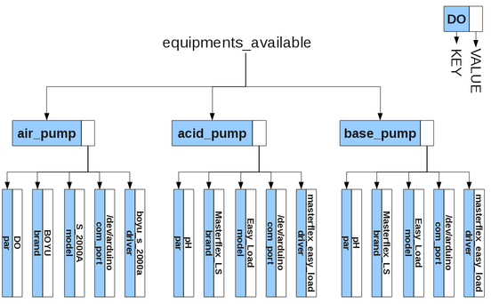
The field Name of equipment is the link between the objects of class State and the objects of class Equipment..
We may use the state transition tables of pH and DO to indicate this relationship.
The module monitor.tcl is dedicated to read data from serial port, store it in database and plot it. While objcont.tcl is in charge of the control actions depending on the state of the parameter monitored.
As the control action may have longer duration than the intervals between data reading we intended to keep these two actions decoupled (asynchronous).
To implement this we defined the variable readings of the dict type to store the readings of the parameters and to be used by the controller module.
The variable is created with the command set readings [dict create].
The procedure updateReadings is called by monitor.tcl to update the variable and receives as parameters the name of parameter (parameter), the time of readout (t) and the value of readout (r).
proc updateReadings { parameter t r } {

    global readings

    dict set readings $parameter t $t
    dict set readings $parameter r $r

}
And the procedure getReading is called inside the method checkState of the objects of the class State and returns a list of two elements (t and r).
proc getReading { parameter } {

global readings

    set t [dict get $readings $parameter t]
    set r [dict get $readings $parameter r]

    return [list $t $r]

}
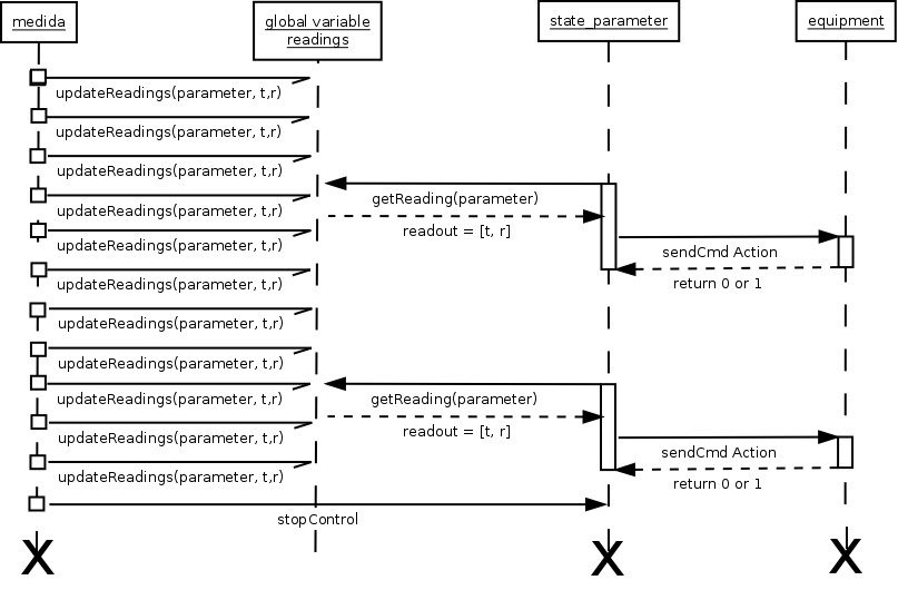
Sequence Diagram indicating the readings variable as a link between the actions of monitoring and control.
Figure 15. Sequence diagram of object interactions from monitor and objccont involved in monitoring and control actions.
The procedure configControl is in charge of creating the objects of State and Equipment class using the list of parameters to be controlled.
proc configControl { list_par_cont } {

    global readings

    set list_obj_equip {}

#list_par_cont: list of parameters to be controlled

    foreach {par max min} $list_par_cont {

#Create the instances of class Equipment

	set list_name_equipment [getNameEquipment $par]

	foreach n_e $list_name_equipment {

	    set info_equipment [getInfoEquipment $n_e]

	    set obj_equipment [equipment new $par \
				   [dict get $info_equipment brand] \
				   [dict get $info_equipment model]]

	    $obj_equipment setName $n_e

	    $obj_equipment setCommunicationPort [dict get $info_equipment com_port]

	    set c [openChannel [$obj_equipment getCommunicationPort]]

#Check if the Arduino board is connected
#The procedure configControl is called by the procedure iniciar_experimento from monitor.tcl
#so if any problem in openChannel command this procedure returns 0 and stop the start of experiment

	    if { $c == "SERIAL_ERRO_OPEN" } {
		puts "configControl -> ERROR - SERIAL_ERRO_OPEN"
		stopControl
		return 0
	    }

	    $obj_equipment setChannel $c

#Initialize de variable key_channel of equipment with 0

	    $obj_equipment setKeyChannel 0

#Load the driver to the instance of equipment

	puts [package require [dict get $info_equipment driver]]

	    lappend list_obj_equip $obj_equipment

	}


#Create the instances of class State

	state create state_$par $par $max $min

	state_$par setState S0

	state_$par setEquip $list_obj_equip

	set list_obj_equip {}

    }

    set list_obj_equipment [info class instances equipment]

    set list_obj_state [info class instances state]

    startControl $list_obj_state

#Return 1 to the caller iniciar_experimento from monitor.tcl

    return 1
}
At the end it calls the procedure startControl passing as parameter a list of objects of class State.
The procedure startControl calls the method start for each object of class State.
proc startControl { list_obj_state } {

    foreach obj_state $list_obj_state {
	puts "startControl Iniciando $obj_state"
	$obj_state start
    }

}
Procedure stopControl call the method stop from all intances of class State and Equipment and destroy all objects.
proc stopControl { {msg Normal} } {

global estado_experimento

    foreach obj_state [info class instances state] {

	catch {$obj_state stop}
	catch {$obj_state destroy}

    }

    foreach obj_equip [info class instances equipment] {

	catch {$obj_equip stop}
	catch {$obj_equip destroy}

    }

    closeChannel

    if { $estado_experimento } {
	parar_experimento $msg
    }

}
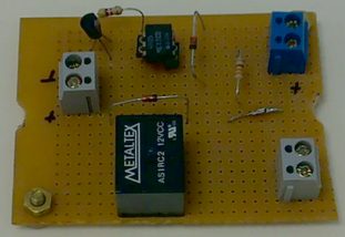
To implement the methods to send commands to air_pump, in class Equipment, we used Arduino to control the power supply of the air pump, or any other device.
We installed the software to develop with Arduino, following the informations on: www.c2o.pro.br/automacao/a6759.htm.
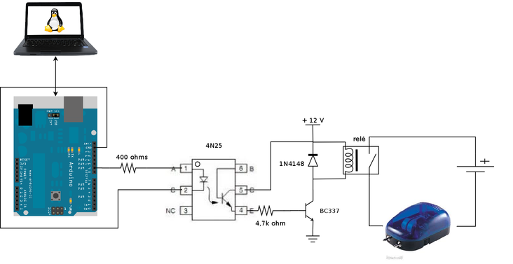
The control circuit in this project uses a relay to turn the air pump ON and OFF.
The relay driver circuit is an interface between the Arduino and the aeration pump and is driven by 5V signal from one of the digital pins on the Arduino which energize an optocoupler (4N25) which in turn will energize the base of a transistor (BC337 ) allowing the triggering of a 12V relay and turning ON the aeration pump, or any other device connected to the relay.
We implemented a code in Arduino to receive a command from serial port with the format: [command];[pin];[value]
[command]: SET (digital (0-1) or analog (PWM 0-255)) or GET (analogRead or digitalRead)
[pin]: D2, D3 ... D12, A0, A1 ... A5
[value]: 0-1, 0-255
The SET command is used on pins configured as OUTPUT. And the GET command is used with the analog and digital pins configured as INPUT.
Examples of command:
SET;D2;0 - set digial pin “D2” to “0”
SET;D3;255 - set digital pin “D3” to “255” in PWM mode
GET;A0 - get the reading of analog pin “A0”
GET;D1 - get the reading of digital pin “D1”
Final version of the sketch:
/*
Final version of the sketch to interpret the commands SET and GET
07/02/2014
*/

char message[15];
char *cmd;
char *pin;
char *value;

char c;
byte length;
byte length_message;

void setup() {

  Serial.begin(9600);
  Serial.flush();
//Available pins
//D2, D3 (PWM), D4, D5(PWM), D6(PWM), D7, D8, D9(PWM), D10(PWM), D11(PWM) e D12
//A0, A1, A2, A3, A4 e A5

//Pins 2-5 are configured as digital input pins,
//and pins 9-12 are configured as digital output pins.

  pinMode(9,  OUTPUT);
  pinMode(10, OUTPUT);
  pinMode(11, OUTPUT);
  pinMode(12, OUTPUT);

  pinMode(2, INPUT);
  digitalWrite(2,HIGH); // enable pull-up resistors

  pinMode(3, INPUT);
  digitalWrite(3,HIGH); // enable pull-up resistors

  pinMode(4, INPUT);
  digitalWrite(4,HIGH); // enable pull-up resistors

  pinMode(5, INPUT);
  digitalWrite(5,HIGH); // enable pull-up resistors
}

void loop() {

  for (int i = 0; i < 15; i++) {
    message[i] = 0;
    }

  if (Serial.available() > 0) {


    //Wait to receive the message
    //with 9600 baud (9600 bits/s = (9600/8) bytes / sec
    //1200 bytes/s = 1200 characters/s = 1200 caractere/1000ms
    //therefore each character takes approx. 1.2 ms to be transmitted
    //50 ms are therefore sufficient for receiving approx. 40 characters

    delay(50);


    length_message = Serial.available();

    if (length_message >= 15) {

      Serial.print("message larger than the limit (15)!");
      Serial.println(length_message);


      for (int i = 0; i < length_message; i++) {
          c = Serial.read();
	 }

    } else {

      for (int i = 0; i < length_message; i++) {
	c = Serial.read();
        if (c != '\n' && c != '\r') {
	  message[i] = c;
        }
      }


      //function which returns the array size
      //but does not count the null '\0' end-of-string character

      length = strlen(message);

      message[length] = '\0'; // message[length] = 0

      cmd = strtok(message, ";");

         if ( (strcmp(cmd, "SET") == 0) || (strcmp(cmd, "set") == 0) ) {
           pin = strtok(NULL, ";");
           value = strtok(NULL, ";");
	   setPin(pin, value);

      } else if (strcmp(cmd, "GET") == 0 || strcmp(cmd, "get") == 0) {

        pin = strtok(NULL, ";");

         getPin(pin);

      } else {

        Serial.println("unknown command");

      }


    }
  }

}


void setPin(char *pin, char *val) {


  if ((pin[0] == 'D') || (pin[0] == 'd')) {

    byte numPin = strtol(pin+1, NULL, 10);

      //O valor do pino digital pode ser HIGH 1 ou LOW 0
      //e a funcao atoi converte a string contida no ponteiro
      //val em um inteiro (ou byte)

      //The value of the digital pins can be HIGH 1 or LOW 0
      //and the function atoi converts the string contained
      //in the pointer val to an integer (or byte)

    byte state = atoi(val);

    digitalWrite(numPin, state);

    //Otra opcao seria
    //if ( (strcmp(val, "HIGH") == 0) || (strcmp(val, "high") == 0) ) {
    //digitalWrite(numPin, HIGH);
    //} else if ( (strcmp(val, "LOW") == 0) || (strcmp(val, "low") == 0) ) {
    //digitalWrite(numPin, LOW);
    //}

    Serial.print("pin:");
    Serial.print(pin);
    Serial.print(";");
    Serial.print("set:");
    Serial.println(state);

  }

}


void getPin(char *pin) {

   byte numPin = strtol(pin+1, NULL, 10);

 if ((pin[0] == 'D') || (pin[0] == 'd')) {

   byte state = digitalRead(numPin);

    Serial.print("pin:");
    Serial.print(pin);
    Serial.print(";");
    Serial.print("state:");
    Serial.println(state);

 } else if ((pin[0] == 'A') || (pin[0] == 'a')) {

 int readout = analogRead(numPin);

    Serial.print("pin:");
    Serial.print(pin);
    Serial.print(";");
    Serial.print("readout:");
    Serial.println(readout);

 }

}
To organize the commands to be sent to the Arduino to start or stop an equipment we created modules (.tm) for each device.
For example, to control the pump aeration (Boyu, Model S 2000a) we use the boyu_s_2000a-0.0.tm file.
Figure 18. Diagram of the components of the respirometer indicating the module (.tm) for sending commands to the Arduino board..
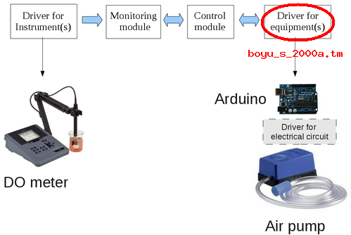
Module boyu_s_2000a-0.0.tm, in the directory lib_equipment, with the namespace “air_pump” in which are defined the procedures: on, off and ig.
#Module with the commands to the equipment BOYU S 2000A

package provide boyu_s_2000a 0.0

puts "Carregado [info script]"

#The variable pin_number defines the pin used to control de device air_pump_I
#any change in the hardware must be updated in the var pin_number

namespace eval air_pump_I {

variable time_out 100 pin_number d9

namespace export on off ig

    proc on {ch} {

variable time_out; variable pin_number

	puts " air_pump_I channel:$ch command SET;$pin_number;1 time_out:$time_out"

	if {[catch {puts $ch "SET;$pin_number;1"}]} {
	puts " ERROR - AIR_PUMP_I sending command ON channel:$ch "
	return 0
        }

	set time_wait 1

	after $time_out {set time_wait 0}

	vwait time_wait

	if {[catch {gets $ch}]} {
	puts " ERROR - AIR_PUMP_I return of command ON:[gets $ch]"
	return 0
	}

        return 1
    }

    proc off {ch} {

variable time_out; variable pin_number

	puts " air_pump_I channel:$ch command SET;$pin_number;0 time_out:$time_out"

	if {[catch {puts $ch "SET;$pin_number;0"}]} {
	puts " ERROR - AIR_PUMP_I sending command OFF channel:$ch "
	return 0
	}

	set time_wait 1

	after $time_out {set time_wait 0}

	vwait time_wait

	if {[catch {gets $ch}]} {
	puts " ERROR - AIR_PUMP_I return of command OFF:[gets $ch]"
	return 0
	}

	return 1

    }

 proc ig {ch} {

variable time_out; variable pin_number

	puts " air_pump_I channel:$ch command IG time_out:$time_out"

	return 1
    }

}
To control two pumps, each one controlled by a digital pin on the Arduino board (air_pump_I pin d9 and air_pump_II pin d10), just add the namespace “air_pump_II” to the same file:
########################################################################
#Namespace air_pump_II with specific commands to device air_pump_II
#The variable pin_number defines the pin used to control de device air_pump_II
#any change in the hardware must be updated in the var pin_number

namespace eval air_pump_II {

variable time_out 100 pin_number d10

namespace export on off

    proc on {ch} {

    	variable time_out; variable pin_number

	puts " air_pump_II channel:$ch command SET;$pin_number;1 time_out:$time_out"

	if {[catch {puts $ch "SET;$pin_number;1"}]} {
	puts " ERROR - AIR_PUMP_II sending command ON channel:$ch "
	return 0
	}

	set time_wait 1

	after $time_out {set time_wait 0}

	vwait time_wait

	if {[catch {gets $ch}]} {
	puts " ERROR - AIR_PUMP_II return of command ON:[gets $ch]"
	return 0
	}

	return 1
    }

    proc off {ch} {

variable time_out; variable pin_number

	puts "air_pump_II channel:$ch command SET;$pin_number;0 time_out:$time_out"

	if {[catch {puts $ch "SET;$pin_number;0"}]} {
	puts " ERROR - AIR_PUMP_II sending command OFF channel:$ch "
	return 0
	}

	set time_wait 1

	after $time_out {set time_wait 0}

	vwait time_wait

	if {[catch {gets $ch}]} {
	puts " ERROR - AIR_PUMP_II return of command OFF:[gets $ch]"
	return 0
	}

	return 1

    }

    proc ig {} {

variable time_out; variable pin_number

	puts "air_pump_II channel:$ch command IG  time_out:$time_out"

	return 1

    }
}
If we want, for example, use a heater to control the temperature we just define another driver for the heater (fame_bio-0.0.tm):
#Module with the commands to the equipment FAME BIO

package provide fame_bio 0.0

puts "Carregado [info script]"

#The variable pin_number defines the pin used to control the heater
#any change in the hardware must updated in the var pin_number

namespace eval heater {

namespace export on off

variable time_out 100 pin_number d11

    proc on {ch} {

variable time_out; variable pin_number

	puts "heater channel:$ch command SET;$pin_number;1 time_out:$time_out"

	if {[catch {puts $ch "SET;$pin_number;1"}]} { return 0 }

	set time_wait 1

	after $time_out {set time_wait 0}

	vwait time_wait

	if {[catch {puts "ARDUINO - HEATER ON: [gets $ch]"}]} { return 0 }

	return 1

    }

    proc off {ch} {

variable time_out; variable pin_number

	puts "heater channel:$ch command SET;$pin_number;0 time_out:$time_out"

	if {[catch {puts $ch "SET;$pin_number;0"}]} { return 0 }

	set time_wait 1

	after $time_out {set time_wait 0}

	vwait time_wait

	if {[catch {puts "ARDUINO - HEATER OFF: [gets $ch]"}]} { return 0 }

	return 1

    }

}
After mounting the box with boards (Arduino and circuit driver), the 12V source for relay and the plug, I did some tests and noticed that the device /tty/USB0 closed suddenly, and reconnected with another number (/dev/ttyUSB1).
Then I included an if test in the class “Equipment” for the equipment to check whether the channel was still open and reopen if necessary:
if {[chan names $channel] != ""} {
		    [[self] getName]::$c $channel
		} else {

		    [self] setChannel [openChannel [[self] getCommunicationPort]]
    puts "************OPENING AGAIN THE SERIAL PORT IN [self]-> $cannel**************"
		    [[self] getName]::$c $channel
		}
But I observed that if I disconnect the USB cable the device /dev/ttyUSB0 disappears but the channel don't close and the commands: tell $channel, eof $channel, chan names $channel and file channels $channel returns the same information, without change.
In the messages: https://groups.google.com/forum/#!msg/wview/YmbFUvmjht0/dgzket-_jbcJ, https://groups.google.com/forum/#!topic/wview/wiE_lHBPN7Y and http://www.linuxquestions.org/questions/linux-newbie-8/usb-port-nn-disabled-by-hub-emi-re-enabling-841593/, I found information about EMI and observed the message in dmesg:
FTDI USB Serial Device converter now attached to ttyUSB1
[15145.280088] hub 2-0:1.0: port 2 disabled by hub (EMI?), re-enabling...
[15145.280098] usb 2-2: USB disconnect, address 18
[15145.280409] ftdi_sio ttyUSB1: FTDI USB Serial Device converter now disconnected from ttyUSB1
...
We used the information at: http://hintshop.ludvig.co.nz/show/persistent-names-usb-serial-devices/ and http://www.redhat.com/magazine/002dec04/features/udev/ to define a persistent, descriptive device name for the Arduino board.
We use as unique identifier the Serial Number:
dmesg

usb 2-1: new full speed USB device using uhci_hcd and address 33
[25696.874956] usb 2-1: New USB device found, idVendor=0403, idProduct=6001
[25696.874963] usb 2-1: New USB device strings: Mfr=1, Product=2, SerialNumber=3
[25696.874968] usb 2-1: Product: FT232R USB UART
[25696.874973] usb 2-1: Manufacturer: FTDI
[25696.874977] usb 2-1: SerialNumber: A100P7VZ
[25696.875145] usb 2-1: configuration #1 chosen from 1 choice
[25696.883016] ftdi_sio 2-1:1.0: FTDI USB Serial Device converter detected
[25696.883062] usb 2-1: Detected FT232RL
[25696.883066] usb 2-1: Number of endpoints 2
[25696.883070] usb 2-1: Endpoint 1 MaxPacketSize 64
[25696.883075] usb 2-1: Endpoint 2 MaxPacketSize 64
[25696.883078] usb 2-1: Setting MaxPacketSize 64
[25696.884055] usb 2-1: FTDI USB Serial Device converter now attached to ttyUSB2

udevadm

# udevadm info -a -n /dev/ttyUSB2 | grep '{serial}' | head -n1
    ATTRS{serial}=="A100P7VZ"
We used the serial number to create an UDEV ruleset that'll make a nice symbolic link for the arduino board.
UDEV rules are usually scattered into many files in /etc/udev/rules.d. So we created a new file called 99-usb-serial.rules with the line:
SUBSYSTEM=="tty", ATTRS{idVendor}=="0403", ATTRS{idProduct}=="6001", ATTRS{serial}=="A6008isP", SYMLINK+="arduino"
And reloaded the rules with the command:
#udevadm control --reload-rules
This is useful because we don't need to worry about the number of the device, we use only /dev/arduino.
The program that is available for download still needs many improvements, but it has been used in our lab and may also be useful for other people.
Thanks to the participants of comp.lang.tcl who helped me understand the concepts of Finite State Machine among many other questions, the community of users and developers of the Arduino board and the large community of Free Software and Open Hardware.
[6] An Instrument could be defined as a device used for measurements and therefore provides some information (qualitative or quantitative) about the system being studied.
An Equipment is used to perform a task but does not provide information about the system under study.
Thus, a pH meter is an Instrument while a pump is a Equipment.